Apparatus
"...K.N.C. Bray
eloquently outlined the essential role of experiments in model development and named
several attributes of ideal experiments. This attributes include a simple flow configuration,
unobstructed optical access, ability to isolate and vary certain parameters relevant to the
testing of models, accurate initial and boundary conditions, and data complete enough that
quantitative comparisons with model calculations can be performed without ambiguity."
Kohse-Hoinghaus et al noted [1].
In the Fig. 1 there is a scheme of the flow in the boundary
layer. The air flow whose velocity is U0 takes place in the
working part of the channel. The lower wall is produced from
porous material and is impregnated with liquid fuel.
Near this wall the longitudinal component U(y) varies from
zero up to the main stream velocity U0. After ignition of the
fuel vapor, the maximum specific temperature distribution T(y)
is reached in the boundary layer in the area of chemical
transformations. The leading edge of the flame is held by
the rib 4 at the channel inlet. The inclination of the upper
lid 1 sets the required law of the main stream velocity U0(x)
for the different values of the acceleration parameter K.
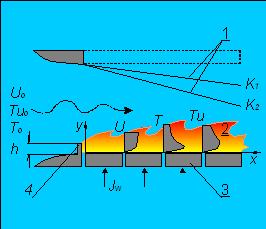
Fig.1. Flow scheme in the boundary layer. 1 - upper lid of the channel;
2 - boundary layer with combustion; 3 - porous plates;
4 - edge to flame stabilize.
The object of the study is characterized by several operating factors, namely: transverse substance flux on the wall , evaporation, combustion, acceleration and increased turbulence. They are absolutely necessary since it makes the process more determined. First, at adiabatic evaporation, the temperature on the wall, and gas and vapor concentrations are clearly preset and do not depend on air flow velocity or its turbulence [2]. Second, the presence of the barrier increases combustion stability, which is extremely important for the investigation of the effects of various gas-dynamic factors (acceleration, turbulence) on the transfer process. Combustion stability furthermore aids in carrying out investigations under the conditions of increased airflow velocity, when the role of natural convection and input of radiation heat transfer decreases. The mentioned specificity of the boundary layer is justified since it characterizes the combustion process in natural conditions as well as technical devices.
Experimental data were obtained in an aerodynamic tube [3] with a 100x100 mm working area at the channel inlet. It allows for studying the boundary layer on various surfaces at different velocities (up to 70 m/sec), turbulence degrees (up to 26%), and longitudinal pressure gradient in the incident air flow with and without combustion. In the experiments without acceleration (dP/dx = 0), the upper lid of the channel was absent. Side walls were transparent and composed of a set of quartz plates. The porous lower surface was formed either by a fill of glass balls with a diameter of ~0.7 mm, or by plates of porous stainless steel with an overall size of 80x80 mm. A fuel supply system provided a constant level of ethanol in the glass ball fill (or in the porous plates), which, due to the action of capillary forces, remained wet during the course of the experiment. The velocity of ethanol evaporation from each element was self-regulated according to the specificity of the heat and mass transfer with combustion zone. In the experiments with an accelerated air flow where dP/dx < 0 the acceleration parameter remained approximately constant along the channel length , the lid (400 mm in length) remained flat, and only its incline changed. Channel height at the inlet was 98 mm, and at the outlet, 98 mm, 70 mm, or 49 mm. Such geometry complies with the values K = 0.7x10⁻⁶, K = 1.3x10⁻⁶ and K = 4.1x10⁻⁶ ; T0 =17 0C.
Consumption of ethanol through each porous plate and the temperature on its surface were measured (Tables 19,20). The concentration of fuel and its combustion products on the evaporating surface were determined according to the wall temperature and gas composition in the near-wall area (Tables 13-14). Data on temperature distribution in the reacting boundary layer were obtained by the platinum-platinum-rhodium thermocouple with a diameter of 50 microns and corrected to eliminate the radiant losses of the probe (Tables 1-11, odd numbers).
The measurements of the distribution of stable substances were carried out by the taking of gas samples at various flame points and with further analysis by gas chromatograph TSVET-102. A gas sample was continuously sucked off from the boundary layer with the use of a quartz probe and periodically supplied to the gas chromatograph inlet. To prevent the losses of condensing components of the gas mixture, the temperature of the sampler probe, the dosing tap of the chromatograph, and the main line binding them, were maintained at 90oC by pumping hot water through the thermostat. The analysis was carried out so that the mix passed the detector twice at consecutive inclusions of columns with sorbents Polysorb-1 and molecular sieves NaX, having different temperatures. The length of the columns and connecting gas-mains were selected under the following condition: when the gas mixture passes through one half of the detector, the pure carrier gas should be in the other half. This served to perform separation of substances specific to hydrocarbon combustion: CO2, C2H5OH, C2H4O, H2O, O2, N2 and CO for single introduction. The duration of the analysis (~5 min) conforms to the measurement pace in the studies of gas content in the boundary layer.
The velocity and turbulence fields were studied with a laser Doppler anemometer (LDA). The anemometer's LADO-2 [4] optical system and the LG-79-1 radiation source (He-Ne)-laser with a power of 15 mW, were located on the platform of the coordinate device over the working section. The range of displacement along the flow was up to 400 mm (error ~0.5 mm); and across the flow from wall up to y=30 mm (error ~0.2 mm). The laser beam (wavelength 632.8 nm), through an acousto-optical cell, was split into two in the horizontal plane. The frequency shift between them was 20 MHz. The beams, with an approximate capacity of 3 mW, entered into the working area through a slot 10 mm wide between disjoined quartz plates of the side wall and focused in an area of intersection with a volume of 0.1x0.1x0.5 mm. For scattering centers, we used particles of quartz with an average modal size of 1 micron; they were introduced into the air flow at the confusor of the aerodynamic tube. Radiation scattered by the particles was taken out of the channel through the slot on the opposite wall and registered with the photomultiplier. In the experiments with a longitudinal pressure gradient, for radiation input and output we used windows with dust-protection. With the same view, instead of porous plates, the renewable fill of glass balls was used. A signal proportional to Doppler frequency shift, (i.e. particles' velocity) was determined with the processor being a tracking filter. Moreover, the device provided the determination of the numerical density of the particles flying through the measurement volume and a monitoring of the signal form U(t). Measurement accuracy of the average values was not worse than 2% (Tables 2-12, even numbers). Tables 17, 18 show some data on velocity pulsations.
Figure 2 shows a working part of our combustion chamber. To study the concentration fields of OH radicals, the method of laser-induced fluorescence (LIF) was used in the mode of signal saturation [5]. The radiation of the solid-state Nd:YAG laser was transformed into the second harmonica and pumped the tunable dye laser (radiation energy - 0.5 mJ/pulse, pulse duration - 15 ns, repetition rate - 10 pulse/sec). The lens focused a ultraviolet radiation on the measurement object, where the density of the laser radiation power exceeded the known value of the saturation threshold and equaled 3x10⁷W/(cm2cm-1). Saturated fluorescence from the focused laser beam's central area with the dimensions of 0.03x0.1x1.0 mm, limited by the inlet slit and diameter of beam waist and diaphragm, went to a monochromator. Time resolution of the electronic registration system was less than the laser pulse duration and amounted to 10 ns.
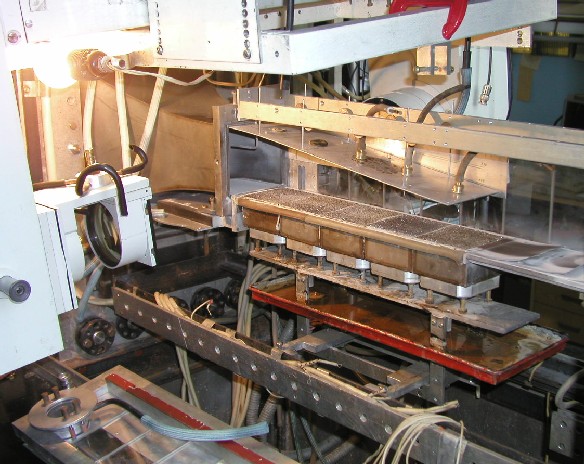
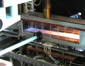
Fig.2. Here are working section and optical system of LDA (left: side wall is removed). Working section adapted for OH radicals' concentration measurements (right). Laser radiation focused in the flame, radiation scattered upwards, accumulated with the objective of the receiving system. Velocity at the channel inlet was about 4 m/s.
The excitation and registration of the OH radical fluorescence were realized in the rotational-vibrational band. The laser wavelength was adjusted on the spectral peak of 311.3 nm. The monochromator with a spectral resolution of 0.3 nm was tuned to the fluorescence peak with a wavelength of 307.5 nm. Calculations show that in the range of temperatures 900-3000K population of the initial level f26 changes by less than 20%. Therefore, use of the specified line for OH excitation provides a fluorescence signal depending not on the temperature, but only on the concentration of these radicals.
Data of monopulse measurements were processed with the computer (see Tables 15, 16) . To obtain absolute concentrations of OH, a signal was calibrated in a diffusive flame of hydrogen as studied earlier by the researcher M.C. Drake and his co-authors [6]. With this view, the conditions of their experiments (their accuracy is +/- 30%) were reproduced. Obtained data of hydroxyl concentration measurements were accepted as standard.
Tables 1-20 show some experimental data, when the inlet velocity was 10 m/s.
References
1. Kohse-Hoinghaus K., Barlow R.S., Alden M., Wolfram J., Proceedings of Combustion Institute 30
(2005) 89-123.
2. B.F. Boyarshinov, E.P. Volchkov, V.I. Terekhov, Siberian Physical and Technical
Journal 3 (16) (1985) 13-22.
3. B.F. Boyarshinov, E.P. Volchkov, V.I. Terekhov, Physics of Combustion and
Explosion (1) (1994) 8-15.
4. Yu.N. Dubnishchev, B.S. Rinkevichus, Nauka, Moscow, 1982.
5. B.F. Boyarshinov, V. I. Titkov, S.Yu. Fedorov, Physics of Combustion and
Explosion 41 (4) (2005) 22-28.
6. M.C. Drake, R.W. Pitz, M. Lapp, C.P. Fenimore, R.P. Lucht, D.W. Sweeney,
N.M. Laurendeau, Proc. Combust. Inst. 20 (1984) 327-335.
Nomenclature
In the Tables below (numeration "98-98", "98-70" or "98-open") marks the height
of channel at the inlet and outlet or the case without top lid.
Tu - turbulence intensity;
x, y (mm) - longitudinal and transverse coordinates;
U, U', (m/s) - longitudinal averaged velocity and its RMS pulsations;
jW (kg/s/m2) - ethanol flux at the wall;
h - (mm) - height of rib.